TBI-VAC / Environment + load

Vacuum & High-Current Slip Rings

Define a vacuum-compatible, high-current or sealed rotary interface for semiconductor equipment, wind pitch systems and crane cable reels.

Typical design brief: Vacuum chucks, coating chambers, pitch drives and marine winches.

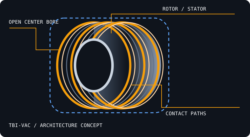
Concept section showing open center bore, annular contact paths, rotor and stator
Architecture concept · illustrative geometry, not a released product drawing.

IMPERIAL / METRIC SELECTION ENVELOPE

Define the bore and every circuit.

These are design request ranges, not an orderable stock specification. Exact dimensions, current derating and maximum speed require a released drawing.

Model / familyThru-bore ID (in / mm)OD × L (mm)Power circuitsSignal / data channelsMax speed (RPM)
TBI-VAC
Configuration-specific circuit schedule
1.0 in / 25.4 mmDrawing review required50 / 100 / 250 / 500 A design requestsSeparate low-noise channel reviewThermal and environment dependent
TBI-VAC
Configuration-specific circuit schedule
2.0 in / 50.8 mmDrawing review required50 / 100 / 250 / 500 A design requestsSeparate low-noise channel reviewThermal and environment dependent
TBI-VAC
Configuration-specific circuit schedule
Metric 100 mm / ≈3.937 inDrawing review required50 / 100 / 250 / 500 A design requestsSeparate low-noise channel reviewThermal and environment dependent
TBI-VAC
Configuration-specific circuit schedule
Metric 200 mm / ≈7.874 inDrawing review required50 / 100 / 250 / 500 A design requestsSeparate low-noise channel reviewThermal and environment dependent
TBI-VAC
Configuration-specific circuit schedule
Metric 300 mm / ≈11.811 inDrawing review required50 / 100 / 250 / 500 A design requestsSeparate low-noise channel reviewThermal and environment dependent

Exact imperial conversions: 0.5″ = 12.7 mm · 1″ = 25.4 mm · 1.5″ = 38.1 mm · 2″ = 50.8 mm · 3″ = 76.2 mm · 4″ = 101.6 mm. Metric 50 / 70 / 100 mm bores remain separate choices.

APPLICATION REVIEW

What determines a workable TBI-VAC?

High vacuum, IP68 immersion, extreme temperature and 500 A are separate design branches. They are not combined standard ratings.

  • Vacuum pressure, outgassing, materials and bakeout
  • Continuous / peak current, voltage and cooling
  • For IP68: depth, duration, medium and rotation duty
Replacing an existing assembly? →
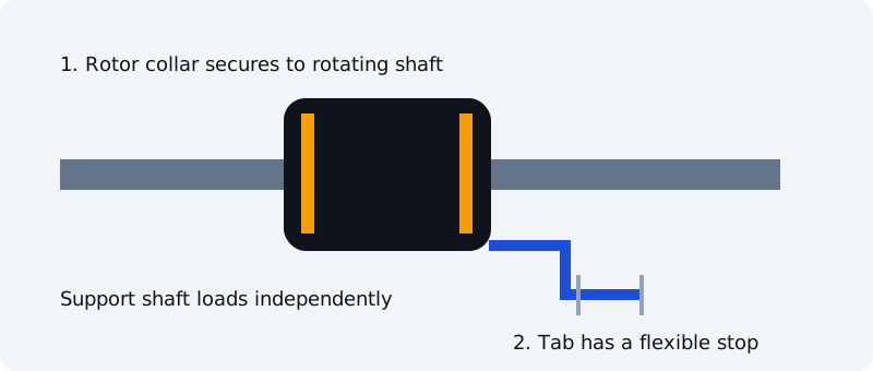
Concept mounting: rotor on independently supported shaft, stator tab restrained with compliance

Give the stator a flexible stop.

For a shaft-mounted design, secure the rotor as its drawing specifies and restrain the stator with an anti-rotation tab that accommodates misalignment. Avoid rigidly locking both sides. Mounting is model-specific; flange and capsule designs may differ.

Read the mounting checklist →

CONNECTORS / LEADS / ENCLOSURE

Send a complete TBI-VAC requirement.

Choose termination, wire length and mounting options below. Displayed accessory amounts are planning allowances; compatibility and final cost are confirmed with the quotation.

30-second configuration brief

Family ranges are reviewed together: selecting a larger bore does not establish high-speed or data-path compatibility. Enter an exact size in notes when choosing a nonstandard bore.

Assembly options

Illustrative accessory allowances, subject to compatibility and written quotation. Two options are preselected; clear either if unnecessary. Connector quantity, circuit count, wire gauge, custom harness work, sealing, shipping and any NRE are priced for the agreed configuration.

Connector and extended-length selections apply only when their corresponding assembly option is checked. Wire material, sealing scope and connector suitability require approval.

No payment is collected. No stock, dispatch date or performance is reserved by this request.

TBI-VAC engineering questions

Does IP68 mean vacuum compatible?

No. Immersion sealing and vacuum material/outgassing requirements are different. Specify and validate the operating environment independently.

Is 500 A available at every bore and speed?

No. Current, heat removal, contact geometry and duty determine feasibility. Provide a complete load profile for engineering review.

Compare adjacent slip ring architectures.

DEFINE THE ROTATING INTERFACE

Start with the bore.
Build the circuit schedule.

Send your shaft size, current, data interface and duty. Request a drawing and configuration-specific quotation.

Request engineering review ↗