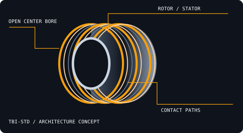
A through-bore slip ring transfers electrical power or signals between stationary and rotating assemblies while leaving a center opening for a shaft or services.
Architecture concept · illustrative geometry, not a released product drawing.
Convert the shaft size before selecting the bore.
Use millimeters = inches × 25.4. Exactly 2 inches is 50.8 mm; a nominal 50 mm bore is a different size. Include shaft tolerance, clearance, runout and the approved mounting method in the drawing review.
Build a channel schedule, not a total ring count.
List voltage, continuous and peak current, signal level, protocol, shield continuity and pinout for every channel. High-current paths need thermal review; Gigabit Ethernet, USB and low-level sensor channels need dedicated integrity criteria.
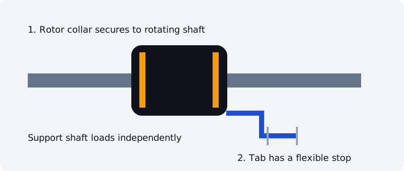
Give the stator a flexible stop.
For a shaft-mounted design, secure the rotor as its drawing specifies and restrain the stator with an anti-rotation tab that accommodates misalignment. Avoid rigidly locking both sides. Mounting is model-specific; flange and capsule designs may differ.
Specify measurement bandwidth and operating conditions for contact resistance variation or sensor noise. For data links, define cable lengths, protocol, speed, traffic and acceptable packet or bit errors. For high-speed work, add balance, bearing temperature and endurance duty.
Keep vacuum and immersion specifications separate.
Vacuum design needs pressure, material outgassing and bakeout inputs. IP68 needs specified immersion conditions. Neither label by itself proves suitability for the other environment.
Collector ring or slip ring?
Terminology varies by industry. For this site the procurement scope is an electrical, signal or hybrid rotary interconnect. Use the circuit schedule and mechanical drawing to define the actual assembly.
DEFINE THE ROTATING INTERFACE
Start with the bore. Build the circuit schedule.
Send your shaft size, current, data interface and duty. Request a drawing and configuration-specific quotation.